


 BOM
BOM Cart
Cart Product Catalog
Introduction
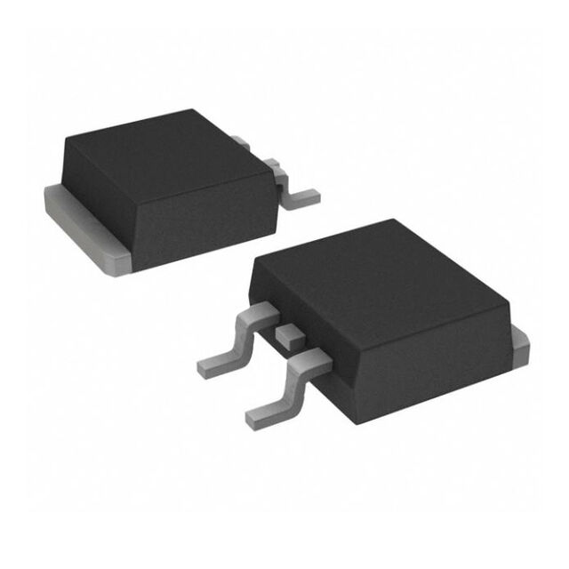
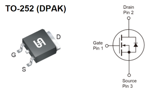
The TSM3N100CP brand Taiwan Semiconductor is a N-Channel Power MOSFET( 1000V, 2.5A, 6Ω ) designed for power switching applications.
It offers a robust combination of high voltage tolerance, low on-resistance (RDS(on)), and fast switching speeds. Making it ideal for power supplies, LED lighting, and motor control. In this article, let's understanding TSM3N100CP features, applications. And how to use it in common electronic projects.
TSM3N100CP picture
Key Features of the TSM3N100CP
100% Avalanche Tested – Ensures reliability under high-energy transient conditions.
Advanced Planar Process – Enhances performance and thermal stability.
Compliant RoHS /WEEE – Environmentally friendly and meets global regulations.
Halogen-Free – Complies with IEC 61249-2-21 for safer PCB manufacturing.
| KEY PERFORMANCE PARAMETERS | ||
| PARAMETER | VALUE | UNIT |
| VDS | 1000 | V |
| RDS(on)(max) | 6 | Ω |
| Qg | 19 | nC |
Applications
· AC/DC LED Lighting – Efficient power switching for LED drivers.
· Power Supplies – Used in SMPS (Switched-Mode Power Supplies) and DC-DC converters.
· Power Meters – Provides accurate power measurement with minimal losses.
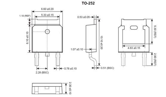
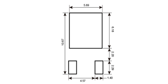
Package Outline Dimensions (Unit: Millimeters)
Suggested Pad Layout
Making Diagram
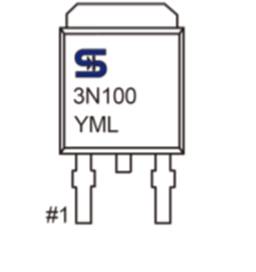
Y= Year Code
M= Month Code for Halogen Free Product
O=Jan P=Feb Q=Mar R=Apr
S=May T=Jun U=Jul V=Aug
W=Sep X=Oct Y=Nov Z=Dec
L= Lot Code(1~9, A~Z)
TSM3N100CP Label Picture

HowTo #1: Using TSM3N100CP in a Buck Converter
Objective:
Design a step-down (Buck) converter using the TSM3N100CP to efficiently reduce a high DC voltage (e.g., 48V) to a lower voltage (e.g., 12V).
Components Required:
· TSM3N100CP MOSFET
· Inductor (e.g., 100µH)
· Diode (Schottky, e.g., MBR20100)
· Capacitor (e.g., 100µF)
· PWM controller (e.g., UC3843)
· Resistors & feedback network
Steps:
1. Connect the MOSFET as the Switching Element
o Drain to input voltage (48V).
o Source to ground via a current-sensing resistor (if needed).
o Gate to PWM controller output.
2. Add the Inductor and Diode
o Connect the inductor between the MOSFET’s drain and the output load.
o Place the diode (cathode to inductor, anode to ground) for freewheeling current.
3. Implement Feedback Control
o Use a voltage divider to sense output voltage and feed it back to the PWM controller.
4. Test and Adjust
o Verify output stability under load and adjust PWM frequency if necessary.
Expected Outcome:
A stable 12V output with high efficiency (~90%) because the MOSFET’s low RDS(on).
HowTo #2: Building a Switch-Mode Power Supply (SMPS) with TSM3N100CP
Objective:
Design a 12V, 5A SMPS for industrial applications using the TSM3N100CP.
Components Required:
· TSM3N100CP MOSFET (as the main switch)
· PWM IC (e.g., TL494)
· High-Frequency Transformer (Ferrite Core)
· Rectifier Diodes (e.g., UF4007)
· Output Filter Capacitors (Low-ESR, 470µF)
Steps:
1. Set Up the Flyback Converter Circuit
o The MOSFET’s Drain connects to the transformer primary winding.
o The Gate is driven by the PWM controller (TL494).
2. Add Snubber Circuit for Protection
o A RCD snubber (Resistor-Capacitor-Diode) across the transformer prevents voltage spikes.
3. Rectify & Filter the Output
o The secondary winding feeds into a bridge rectifier + capacitor filter for clean DC output.
4. Implement Feedback for Voltage Regulation
o A voltage divider provides feedback to the PWM IC, ensuring stable 12V output.
Expected Outcome:
A compact, efficient SMPS delivering 12V at 5A, suitable for industrial automation systems.
HowTo #3: Overcurrent Protection Circuit Using TSM3N100CP
Objective:
Create a fast-acting overcurrent protection circuit for a 24V, 10A power system.
Components Required:
· TSM3N100CP MOSFET (as the power switch)
· Current-Sense Resistor (0.05Ω, 5W)
· Comparator (e.g., LM393)
· Reference Voltage (e.g., 0.5V using a Zener diode)
Steps:
1. Sense Current with a Low-Value Resistor
o Place a 0.05Ω shunt resistor in series with the load.
2. Compare Voltage Drop with Reference
o The LM393 comparator triggers when the sensed voltage exceeds 0.5V (10A limit).
3. Cut Off Power via MOSFET
o The comparator output disables the MOSFET’s Gate, shutting down the circuit instantly.
4. Test with Overload Condition
o Apply a 12A load and verify the circuit trips within milliseconds.
Expected Outcome:
A reliable overcurrent protection system that prevents damage to sensitive electronics.