




 BOM
BOM Cart
Cart Product Catalog
The 4N35 is one of the most widely used general-purpose optocouplers in electronics. Designed to transfer electrical signals between two isolated circuits using light, providing electrical isolation while still allowing signal communication.
This makes it extremely useful in microcontroller interfaces, switching power supplies, and noise-sensitive digital systems.
4. 4N35 Alternatives/Equivalents
5. How to Use 4N35 Optocoupler?
8. Difference Between 4N25 and 4N35
9. Frequently Asked Questions [FAQ]
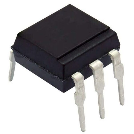
What is IC 4N35?
The 4N35 IC is a general-purpose optocoupler used for electrical isolation between two circuits. It consists of a gallium arsenide infrared emitting diode that acts as the input side and drives a silicon phototransistor on the output side. Both components are enclosed in a standard plastic six-pin dual-in-line (DIP-6) package. When current flows through the LED, it emits infrared light, which is detected by the phototransistor to produce a corresponding electrical signal. The chip allows signal transmission without direct electrical connection, ensuring protection from high voltage, noise, and ground loop issues in electronic circuits.
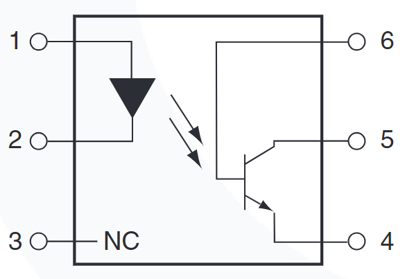
4N35 Pinout and Functions
Comes in a 6-pin DIP package with the following pin configuration:
Pin No. | Name | Description |
1 | Anode | This is the positive terminal of the internal infrared LED. Require a current-limiting resistor when driving it from a voltage source. |
2 | Cathode | This is the negative terminal of the infrared LED. It completes the input LED circuit and usually connect to ground or return path. |
3 | NC | This pin has no internal electrical connection. Not use in circuit design and should be left floating. |
4 | Emitter | This is the emitter terminal of the internal phototransistor. Commonly connect to ground in switching applications. |
5 | Collector | This is the collector output pin. Typically connect to a pull-up resistor or supply voltage to obtain output signal switching. |
6 | Base | This is the base terminal of the phototransistor. Usually left unconnected but can use for sensitivity or noise control in special designs. |
4N35 Schematic
4N35 Specifications
Below is a summarized specification table:
Parameter | Value |
Device Type | Optocoupler (Opto-isolator) |
Number of Channels | 1 |
Input Type | Infrared LED (DC drive) |
Output Type | Phototransistor with Base |
Package Type | 6-Pin DIP (Through Hole) |
Isolation Voltage | 5300 Vrms (typical) |
Forward Voltage (Vf) | 1.18 V (typical) |
Forward Current (If) | 60 mA to 100 mA (max depending on variant) |
Current Transfer Ratio (CTR) | ≥ 20% @ 10 mA (typical 100% for high-grade versions) |
Collector-Emitter Voltage (VCEO) | 30 V (max) |
Collector-Emitter Saturation Voltage | 300 mV – 500 mV (max) |
Turn-On Time | ~2 µs (typical) |
Turn-Off Time | ~2 µs (typical) |
Operating Temperature | -55°C to +100°C |
Mounting Type | Through Hole |
Output Configuration | Transistor output with base access |
4N35 Package
The 4N35 optocoupler is available in two common package types:
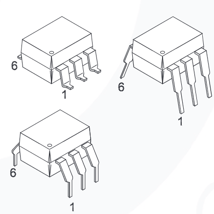
DIP 6-Pin (Dual In-Line Package):
This is the most widely used version. A through-hole package designed for PCB mounting, easy prototyping, and breadboard compatibility. It provides strong mechanical stability and commonly use in industrial and educational electronics.
SMT 6-Pin (Surface Mount Package):
This version is designed for compact and high-density PCB layouts. Suitable for automated assembly processes and modern compact electronic devices where space saving is important.
4N35 Alternatives/Equivalents
PC817
The PC817 optoisolator is one of the most common alternatives. It features a transistor output, 1-channel configuration, and around 5000 Vrms isolation voltage. Widely used in microcontroller circuits, switching power supplies, and signal isolation applications because its low cost and compact design.
6N137
The 6N137 optocoupler is a logic output type device designed for high-speed digital communication. It supports data rates up to 10 MBd, uses an open-drain output, and provides 5300 Vrms isolation with high 1 kV/µs CMTI performance, making it suitable for fast switching and noise-sensitive digital systems.
LOC110
The LOC110 optocoupler is a photovoltage-type isolator with 3.75 kV isolation voltage and a 1-channel configuration in an 8-DIP package. Commonly used in precision analog isolation and feedback control circuits where require stable linear response.
4N36
The 4N36 optoisolator is a close family member of the 4N35 with improved isolation of 5.3 kV and a phototransistor output with base access. Used in industrial control systems and applications requiring higher voltage isolation and flexibility in biasing.
4N25
The 4N25 optoisolator is another widely used equivalent in the same family. It offers 5 kV isolation, transistor output with base pin, and commonly use in general-purpose isolation circuits. Slightly lower in performance compared to the 4N35 in some configurations but remains a popular substitute.
How to Use 4N35 Optocoupler?
Use it to isolate a low-voltage control circuit from a high-voltage or noisy circuit while still allowing signal transmission using light.
1. Basic Connection Principle
The component has two sides: the input side (LED, Pin 1 and Pin 2) and the output side (phototransistor, Pin 4, Pin 5, and Pin 6).
2. Input Side Wiring (LED Side)
Connect Pin 1 (Anode) to the control signal through a current-limiting resistor, while connect Pin 2 (Cathode) to ground. When current flows through the LED, it emits infrared light.
3. Output Side Wiring (Transistor Side)
Connect Pin 5 (Collector) to Vcc through a pull-up resistor, and connect Pin 4 (Emitter) to ground. When the LED is ON, the phototransistor conducts and pulls the output LOW.
4. Working Principle
When apply an input signal, the infrared LED turns ON and emits light. This light activates the phototransistor, causing it to conduct and transfer the signal to the output side without any direct electrical connection.
5. Typical Application Use
The 4N35 commonly use for microcontroller GPIO isolation, relay driving circuits, switching AC loads, and protecting sensitive digital systems from noise or high voltage interference.
6. Important Design Tips
Must always use a series resistor with the input LED to limit current. Typical LED drive current is 5–10 mA. Recommend a pull-up resistor of 4.7kΩ to 10kΩ at the output for stable operation. Pin 6 (Base) is usually left unconnected unless require special control.
IC 4N35 Application
Power Supply Regulators
Commonly use in switching power supplies (SMPS) to provide feedback isolation between the high-voltage output stage and the low-voltage control circuit. This ensures stable regulation while maintaining safety isolation.
Digital Logic Inputs
Use to interface noisy or high-voltage digital signals with low-voltage logic circuits. The optocoupler protects sensitive logic devices from voltage spikes and electrical noise.
Microprocessor Inputs
The 4N35 helps protect microcontroller GPIO pins by isolating external circuits. This prevents damage caused by voltage surges, incorrect wiring, or ground potential differences.
Industrial Control Systems
In PLC and automation systems, the component provides safe electrical isolation between control units and field devices. This improves system reliability and operator safety in industrial environments.
Motor Drivers
Widely use in motor control circuits to separate low-power control signals from high-power driver stages such as relays, triacs, or transistors, reducing interference and improving protection.
Signal Isolation Circuits
Also use the circuit to eliminate ground loop noise in communication and analog signal systems. It ensures clean signal transmission between different ground potentials without direct electrical connection.
4N35 Opto Isolator Feature
The opto coupler offers reliable electrical isolation and stable signal transfer performance for industrial and electronic applications.
Current Transfer Characteristics
The minimum current transfer ratio (CTR) at IF = 10 mA and VCE = 10 V is an important performance indicator. For selected versions such as 4N35M, 4N36M, and 4N37M, the CTR can reach up to 100%, meaning the output transistor can conduct an output current equal to the input LED current under ideal conditions.
Safety and Regulatory Approvals
The component meets strict international safety standards for high-voltage isolation applications. It is certified under UL1577, providing 4,170 VAC RMS isolation for 1 minute, ensuring safe operation in high-voltage environments. It also complies with DIN-EN/IEC60747-5-5, offering a peak working insulation voltage of 850 V, making it suitable for industrial control, power electronics, and safety-critical isolation systems.
Difference Between 4N25 and 4N35
Although both devices belong to the same optocoupler family, there are key differences:
Feature | 4N25 | 4N35 |
CTR (Min) | ~20% @ 10mA | ~100% @ 10mA (higher variants) |
Isolation Voltage | ~4170 Vrms | ~5300 Vrms |
VCE Saturation | ~300 mV | ~500 mV |
Forward Current | ~60 mA | ~100 mA |
Speed | ~2 µs | ~2 µs |
Output Type | Transistor with base | Transistor with base |
Key Insight:
4N35 generally provides higher current transfer capability and stronger isolation
4N25 is slightly more efficient in saturation voltage in some variants
4N35 Datasheet PDF
For designers, can check data sheet for more details.
Frequently Asked Questions [FAQ]
What does a 4N35 do?
It provides electrical isolation between two circuits using an infrared LED and a phototransistor, allowing safe signal transfer without direct electrical connection.
What is a substitute for 4N35?
Common substitutes include PC817, 4N25, 4N36, and 6N137, depending on speed and isolation needs.
What is the difference between 4N25 and 4N35?
4N35 typically offers higher isolation voltage and better current transfer ratio compared to 4N25.
What is the input voltage of 4N35 optocoupler?
The input LED typically operates around 1.2V to 1.4V forward voltage, depending on current.
What is the maximum input current of 4N35?
The maximum forward current is typically 100 mA, but most designs use 5–20 mA for safe operation.
What is 4N35 used for?
Used for signal isolation in power supplies, microcontroller interfacing, industrial control, and noise-sensitive circuits.
What is the difference between PC817 and 4N35?
PC817 is generally smaller, cheaper, and lower power, while 4N35 offers higher isolation voltage and is more robust for industrial applications.
Conclusion
The 4N35 optocoupler remains a reliable and widely used isolation component in electronics. With its simple structure, strong isolation capability, and flexible transistor output, suitable for both beginner and industrial-level designs.
Whether used in microcontroller protection, power supply feedback loops, or industrial signal isolation, the 4N35 continues to be a dependable choice for safe circuit design.
Read More:
1. MAX232 IC: Datasheet, Features, Applications, and Pinout
HOT NEWS
TP4056 Charging Module Pinout, Working, and Applications
TP4056 Charging Module Pinout, Working, and Applications
2026-01-23
LR41 Battery Guide: Specifications, Equivalents, and Uses
LR41 Battery Specifications, Equivalents, and Uses
2025-12-14
Understanding The CD4051 Analog Multiplexer
CD4051 analog multiplexer
2025-06-30
Understanding A 0603 Resistor
0603 resistor,dimensions,marking code, values
2025-05-29
MT3608 Boost Converter - An In-Depth Guide
MT3608 Boost Converter
2025-09-04
Complete Guide to the 220 Ohm Resistor
220 Ohm Resistor
2025-07-28
The 0402 Resistor: A Comprehensive Guide
0402 Resistor
2025-05-06
Mini MP1584 DC-DC 3A Buck Converter Module: Complete Guide
Mini MP1584 DC-DC 3A Buck Converter Module: Complete Guide
2026-03-26
Guide To The XL6009 Boost Converter
XL6009 Boost Converter
2025-09-05
What Is A 1206 Resistor?
1206 resistor dimensions,footprint,value
2025-06-05