


 BOM
BOM Cart
Cart Product Catalog
The XL6009 is a versatile and efficient DC-DC boost converter ideal for stepping up or down voltage in various applications. Manufacture by Xlsemi, it offers a wide input voltage range, high efficiency, and several protection features. Commonly use this chip in automotive systems, portable electronics, and industrial devices. With its ability to generate both positive and negative output voltages, the XL6009 is a go-to solution for reliable voltage conversion. Whether you're building power supplies for Arduino projects, LED drivers, or notebook car adapters, the converter offers stability and flexibility for your design needs.
2. Features of XL6009 Boost Converter
3. XL6009 Datasheet Specifications
4. XL6009 Buck Boost Converter Working Principle
5. XL6009 IC Applications and Applicable Occasion
6. DC DC Step up Converter Buck Boost XL6009 Module 4A
7. Frequently Asked Questions [FAQ] About XL6009 Chip
What is the XL6009?
A highly flexible DC/DC converter design to handle a wide range of input voltage and provide either positive or negative output voltages. A current mode, fixed-frequency device that can operate in different configurations, such as boost, flyback, SEPIC, or inverting converter modes. This versatility makes it ideal for a variety of applications, including portable electronic equipment. The converter integrates an N-channel power MOSFET and a fixed frequency oscillator, both of which ensure stable operation across varying input and output voltages. Its robust design makes it particularly well-suited for situations where need reliable and efficient voltage conversion.
Features of XL6009 Boost Converter
The boost converter design with a set of features that enhance its performance and make it suitable for numerous power conversion tasks. The converter has a wide input voltage range that spans from 5V to 32V, making it adaptable to various systems that operate on different voltage levels. This flexibility allows users to power their devices from different sources without the need for additional power management circuitry.
One of the key features of the chip is its ability to generate either positive or negative output voltages by adjusting the feedback pin. This can be particularly useful in applications that require both types of outputs. Moreover, the current mode control ensures that the converter provides excellent transient response. This means that even during sudden changes in load, the voltage remains stable without noticeable fluctuations, which is necessary for powering sensitive electronics.
The 1.25V reference adjustable version of the converter chip allows the user to fine-tune the output voltage to meet the specific needs of the application. It also has a fixed switching frequency of 400 kHz, which design to improve efficiency and minimize noise, making the XL6009 ideal for high-performance tasks that require precision.
The converter supports a maximum output current of 4A, providing more than enough power for mid to high-power applications. It also comes equipped with built-in over-voltage protection that shields the circuit from damaging voltage spikes, ensuring longevity and reliability. The excellent line and load regulation ensure that the output voltage remains stable despite fluctuations in the input voltage or load changes. Additionally, the EN pin TTL shutdown capability allows for simple control over the converter, enabling it to turn off when not in use to conserve power.
The internal optimized power MOSFET reduces the need for external components, contributing to a more streamlined design and reducing the complexity of the system. With efficiencies of up to 94%, the circuit operates with minimal power loss, making it a highly efficient solution for power conversion. The converter also comes with built-in frequency compensation, soft-start, and thermal shutdown functions, which provide an extra layer of protection and stability during operation. The current limit function ensures that the converter does not draw excessive current, protecting both the IC and the components in the circuit.
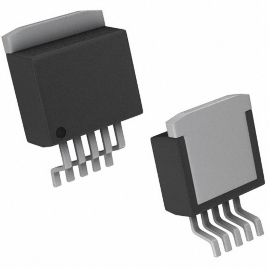
Finally, the TO263-5L package, which is ideal for efficient heat dissipation and easy integration into a variety of designs. These features make the converter an excellent choice for applications requiring efficient and reliable voltage conversion, including portable electronics, automotive systems, and industrial power supplies.
XL6009 Equivalent:
Have several equivalents in the market that offer similar functionality, but with differences in performance characteristics such as input voltage range, current rating, and application suitability. Here’s a comparison with its notable counterparts:
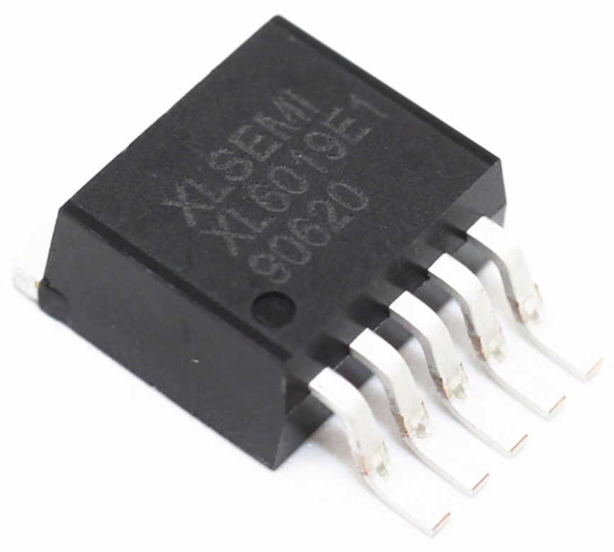
XL6019:
An upgraded version of the XL6009 with a higher maximum current rating of 5A, compared to the XL6009’s 4A. It also supports a higher voltage range of up to 60V, making it more suitable for high-power applications. While the XL6009 is better suited for medium-power projects, the XL6019 can handle more demanding loads. The part of the same Xlsemi family, so it shares the current mode control and fixed frequency oscillator design principles.
LM2577:
Another popular DC-DC converter, but it has a lower current rating of 3A compared to the XL6009’s 4A. It design primarily for step-up (boost) applications and operates with an input voltage range of 3.5V to 40V, which is somewhat more restrictive than the XL6009's 5V to 32V input range. However, the LM2577 is a widely use and trust device for medium-power applications and know for its simple design and ease of use.
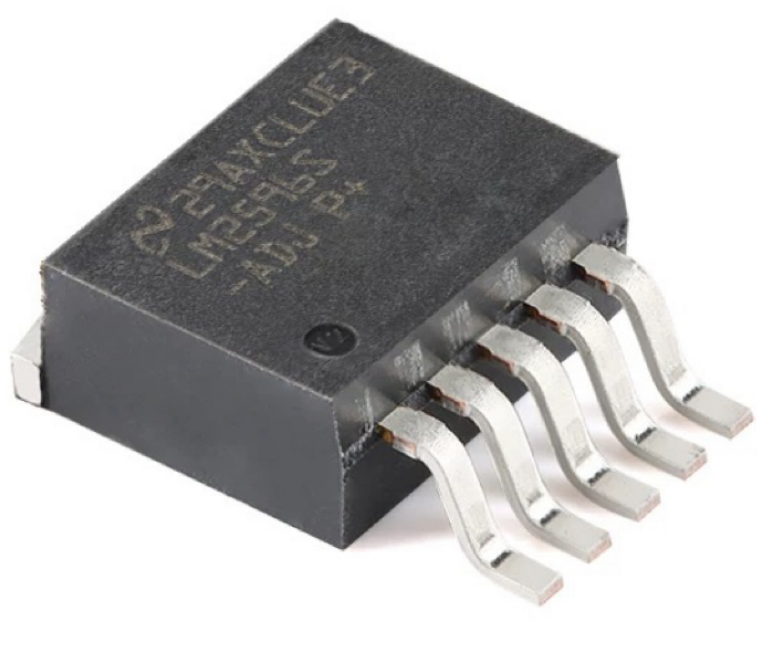
LM2596S:
A step-down (buck) converter, unlike the XL6009 which is a boost converter. It can handle 3A of output current, making it suitable for lower-power applications compare to the XL6009, which supports up to 4A. It operates with an input voltage range of 4V to 40V and generally use when the application requires voltage step-down rather than step-up. The LM2596S is ideal for applications where efficiency is paramount and low heat generation is necessary, but it’s limited to buck operations and lower output currents.
The XL6019 is the closest design but offers a higher current rating and a wider voltage range.
The LM2577 and LM2596S are both step-down converters, so they are not direct substitutes for the XL6009's step-up functionality.
The XL6009 stands out with its 4A output capability and versatility, being able to function in various topologies such as boost, flyback, SEPIC, or inverting converters.
Depending on the specific application, one of these alternatives may be more appropriate, especially if require higher current handling or different voltage conversion modes.
Comparison of XL6009 and Its Equivalents
Part No. | XL6009 | XL6019 | LM2577 | LM2596S |
Current Rating | 4A | 5A | 3A | 3A |
Input Voltage Range | 5V~32V | 5V~60V | 3.5V~40V | 4V~40V |
Output Voltage Range | Adjustable (Positive /Negative) | Adjustable (Positive /Negative) | Adjustable (Positive Only) | Adjustable (Positive Only) |
Switching Frequency | 400kHz | 400kHz | 52kHz | 150kHz |
Efficiency | 94% | 94% | 90% | 90% |
Voltage Conversion | Step-up, Step-down (buck-boost) Inverting | Step-up, Step-down (buck-boost) Inverting | Step-up (boost) | Step-down (buck) |
XL6009 Datasheet Specifications
To dive deeper into the technical details, the XL6009 PDF datasheet is the ultimate resource. It contains a complete list of specifications, including input and output voltage ranges, efficiency ratings, and current capabilities. From the data sheet, users can understand the complete performance characteristics of the converter and how to integrate it effectively into their designs. The converters can operate with input voltages between 5V and 32V, making it highly versatile for a wide array of applications.
Pin Descriptions
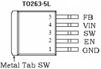
The boost converter has five pins, each serving a specific function. Here’s a detailed description of each pin:
1. GND: This is the ground pin for the device, connect to the system’s ground. All other voltages (input and output) reference to this pin. Proper grounding is essential for stable operation.
2. EN: The enable pin (EN) use to turn the device on or off. When this pin drives high (usually with TTL logic), the XL6009 is active, and voltage conversion occurs. If this pin drive low, the device is disabled, and no voltage conversion happens. If left floating, it defaults to high and the device enable.
3. SW: The switch output pin (SW) connect to the inductor in the boost converter configuration. It acts as the high-side switch that toggles between high and low to store and release energy in the inductor. The SW pin is necessary for voltage boosting as it controls the timing of energy transfer.
4. VIN: The input voltage pin (VIN) is where you supply the DC voltage to the XL6009. The input voltage can range from 5V to 32V, depending on the specific application. Typically place a suitable capacitor near the VIN pin to smooth out the input power and eliminate noise. The quality of the input power directly affects the efficiency and stability of the output voltage.
5. FB: The feedback pin (FB) use to monitor and regulate the output voltage. It senses the voltage at the output and adjusts the switching duty cycle to maintain the desired output level. The Typically connect FB pin to a resistor divider network that sets the output voltage based on the following feedback threshold of 1.25V. By changing the values of the feedback resistors, you can adjust the output voltage of the converter.
These five pins work together to provide stable, efficient power conversion, making the chip a flexible solution for various voltage boosting applications. Proper use of these pins allows you to control and optimize the performance of the converter in your circuit.
Pin Configurations of XL6009 Boost Converter
The chip design to step up input voltages to a higher output voltage. To configure it properly, follow these steps:
1. Input Capacitors (C_in): Place a capacitor near the VIN pin (e.g., 10µF) to filter noise and stabilize the input voltage.
2. Inductors (L): Choose a suitable inductor (typically 10µH). This component is key to the voltage boosting process.
3. Diodes (D): Use a Schottky diode (e.g., 1N5819) to ensure minimal forward voltage drop and efficient operation.
4. Output Capacitors (C_out): Place a capacitor (e.g., 47µF) near the VOUT pin to smooth out the output voltage and reduce ripple.
5. Feedback Resistors (R1, R2): Use a resistor divider network to set the desired output voltage using the FB pin.
The output voltage will depend on the values of the resistors R1 and R2. By adjusting these resistors, you can fine-tune the output to your desired level.
This configuration allows you to design and implement a functional Boost Converter with adjustable output voltage suitable for a wide range of applications.
XL6009 Buck Boost Converter Working Principle
A versatile DC-DC converter that can function in various modes, including boost, buck, buck-boost, and inverting configurations. This allows the chip to efficiently step up, down, or invert the input voltage to achieve the desired output.
1. Basic Operation
The working principle of the Buck-Boost Converter revolves around its ability to store energy in an inductor and then release it in a controlled manner to achieve the desired output voltage. The converter uses an N-channel MOSFET as a switch to control the flow of current through the inductor. The switching frequency is typically fixed at 400kHz.
When the switch (MOSFET) is on, the inductor stores energy by creating a magnetic field.
When the switch is off, the energy stored in the inductor release to the output, typically via a diode that prevents reverse current flow.
The feedback loop constantly adjusts the duty cycle of the switch to maintain a stable output voltage, regardless of fluctuations in the input voltage or load conditions.
2. In boost mode, the input voltage is lower than the desired output voltage. The XL6009 increases the input voltages to a higher output voltage by storing energy in the inductor when the switch is on and releasing it when the switch is off. The output voltage is higher than the input, and the converter operates with a duty cycle greater than 50%.
3. In buck mode, the input voltage is higher than the desired output voltage. The XL6009 reduces the input voltage by storing energy in the inductor during the "on" period and releasing it in a controlled manner during the "off" period. The output voltage is lower than the input, and the converter operates with a duty cycle less than 50%.
4. The buck-boost mode is a combination of both buck and boost operations. In this mode, the XL6009 is capable of converting the input voltage to a higher or lower output, depending on the input and output conditions. This is useful when the input voltage can vary around the desired output level. The converter adjusts its duty cycle to achieve the desired output voltage, whether the input is higher or lower.
For example:
If the input voltage is higher than the desired output, the converter works as a buck converter to step down the voltage.
If the input voltage is lower than the desired output voltage, the converter works as a boost converter to step up the voltage.
5. Feedback Control
The feedback pin (FB) plays a role in regulating the output voltage. It senses the output voltages and adjusts the duty cycle of the switch to ensure that the output level remains stable, even as the input voltages and load conditions change. The feedback voltage typically set to 1.25V, and by adjusting external resistors in the feedback network, you can set the desired output voltage.
6. Switching Control
The MOSFET in the XL6009 control by an internal fixed-frequency oscillator that operates at 400kHz. The switch toggles on and off at this frequency to efficiently transfer energy to the output. The frequency of operation ensures that the inductor charges and discharges at a rate that optimizes power efficiency while minimizing electromagnetic interference (EMI).
In summary, the XL6009 buck-boost converter works by continuously switching between on and off states, transferring energy to the output via an inductor and a diode. Its feedback control ensures that the desired output voltage maintain, regardless of whether the converter is in boost, buck, or buck-boost mode. This flexibility makes the XL6009 ideal for applications where require the input voltage can vary, and a stable output voltage.
XL6009 IC Applications and Applicable Occasion
The chip is a versatile and efficient DC-DC converter IC with a wide range of applications. Its ability to operate in different modes (boost, buck-boost, and inverting) makes it highly adaptable for various power conversion needs. Here are some key applications:
1. EPC / Notebook Car Adapter
Often use in EPC (Electronic Power Converters) and notebook car adapters as its ability to efficiently step up or down voltage. When use in car adapters, it can convert the 12V or 24V supply from a car battery to the 19V or 20V typically required by laptops. The buck-boost capability of the chip allows it to maintain stable output voltage even when the input fluctuates, which is common in car environments.
2. Automotive and Industrial Boost / Buck-Boost / Inverting Converters
In automotive and industrial applications, the chip widely use in boost and buck-boost converters for powering sensitive electronics. Its ability to step up or down voltage makes it ideal for automotive systems that require conversion between 12V or 24V automotive battery systems and various power rails (e.g., 5V, 12V, 15V). Additionally, it can use for inverting converters when require a negative voltage in certain industrial control circuits.
Its flexibility in working with different input and output voltage combinations makes it suitable for applications such as powering sensors, actuators, control circuits, or DC motors in industrial settings.
3. Portable Electronic Equipment
The circuit is highly effective in portable electronic devices where need compact, reliable, and efficient power conversion. For instance, it can use in power banks, portable chargers, and battery-operated devices. The chip can convert lithium-ion battery voltages (commonly 3.7V to 4.2V) to higher output (such as 5V for USB-powered devices), ensuring efficient energy use and long battery life.
Additionally, its high efficiency (up to 94%) and compact TO263-5L package make it ideal for power-sensitive portable applications where space and energy conservation are critical.
The converter is a versatile power conversion solution that caters to a variety of use cases, from automotive and industrial systems to portable electronics. Its efficient, adaptable nature ensures that it remains a reliable choice in applications requiring stable voltage conversion in fluctuating conditions.
DC DC Step up Converter Buck Boost XL6009 Module 4A
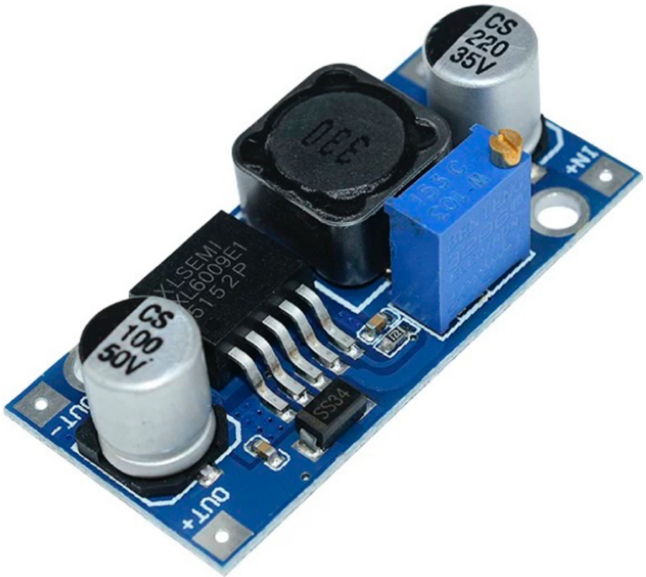
The Module 4A is a highly versatile DC-DC converter that supports boost, buck-boost, and inverting voltage configurations. With an input voltage range from 5V to 32V, it can efficiently convert lower voltages to higher ones (boost mode) or lower-higher voltages to more manageable levels (buck mode), while the buck-boost modes allows it to handle cases where the input voltage is either higher or lower than the desired output.
Common uses of the XL6009 Module include powering portable power supplies, LED drivers, battery charging circuits, and solar power systems. Its adjustable output voltage makes it particularly versatile, allowing for output levels such as 5V, 9V, 12V, and others, depending on the specific application. It widely use in Arduino and Raspberry Pi projects, where require reliable and efficient power conversion. Additionally, the converter module is a popular choice for automotive electronics and car adapters that need stable voltage regulation despite fluctuating input sources.
The compact design and easy-to-use interface of the XL6009 Module 4A make it perfect for a wide variety of DIY projects, industrial applications, and portable electronics, offering a simple solution to maintain consistent power in challenging voltage conditions.
XL6009 20W Adjustable DC-DC Buck Boost Converter With Digital Display Non-Isolated Step Up Evaluation Board
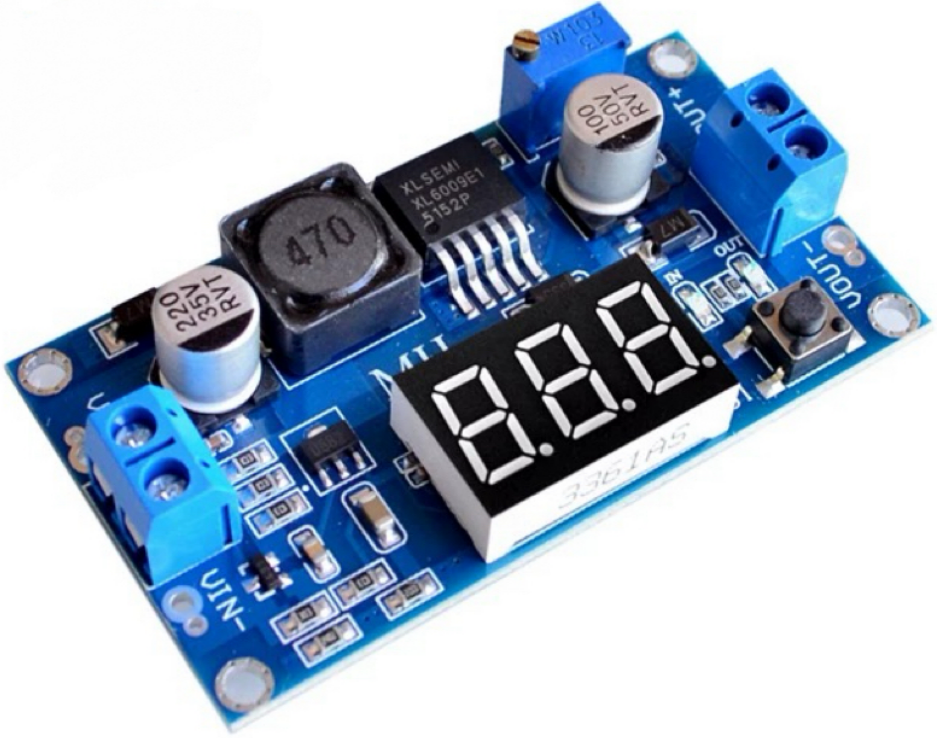
The 20W Converter with led driver is a powerful and efficient DC-DC step-up module that allows users to boost low input voltages to higher output. This module specifically design for applications requiring an adjustable output, with a power rating of up to 20W, making it suitable for a wide range of tasks such as power supply regulation, battery charging, and LED driving. The inclusion of a digital display provides real-time feedback of the output voltage and current, allowing for more precise adjustments and monitoring.
The module accepts input voltages typically ranging from 5V to 24V, making it compatible with various power sources such as batteries, solar panels, or DC power adapters. The output voltage is adjustable from 5V to 35V, allowing the converter to power different types of devices that require various voltage levels.
Capable of providing up to 20W of output power, the module can handle moderate to high power loads, making it suitable for devices that require higher energy consumption. The digital display shows the real-time output voltage and current, enabling accurate and easy monitoring of the converter’s performance without the need for external measurement tools.
The converter design to be highly efficient (often up to 90% or higher), reducing energy losses and ensuring minimal heat generation during operation. This is especially necessary in battery-powered and portable applications. The module also includes built-in over-voltage, over-current, and thermal protection, ensuring safe operation in various environments. The over-voltage protection prevents damage to connected devices by stopping the converter if the output voltage exceeds safe levels.
This module is ideal for creating portable power supplies, such as power banks or battery-powered charging stations. It ensures stable voltage conversion for devices such as smartphones, tablets, and small appliances. Also suitable for charging batteries in devices that require a stable and adjustable charging voltage, including Li-ion or Li-Po batteries. The module is perfect for powering microcontroller-based projects, such as those involving Arduino and Raspberry Pi, where the voltage needs to convert to a specific level for stable operation. Additionally, it can power LED-strips or LED driver, especially in applications requiring constant current and voltage for high-power lighting. The module can also step up the voltage from a solar panel to a desired level for use in various applications such as solar-powered lights or solar chargers.
The DC-DC boost converter works by using an inductor, switching transistor (MOSFET), and diode to store and release energy, boosting the input voltage to a higher output. When the switch (MOSFET) close, current flows through the inductor, storing energy in the form of a magnetic field. When the switch opens, the inductor releases the stored energy to the output capacitor through the diode, raising the voltage to the desired level. The feedback control loop adjusts the duty cycle of the switching transistor to regulate the output voltage based on the user's input settings. The digital display continuously monitors and displays the output voltage and current, providing real-time information to the user for better control.
The module offers precise voltage adjustment with the digital display, providing better control over the output voltage and current settings.
7. Frequently Asked Questions [FAQ] About XL6009 Chip
What is the use of XL6009?
A versatile DC-DC converter use primarily for boosting or stepping up input voltages. It can also function as a buck-boost or inverting converter, allowing for both step-up and step-down voltage regulation. Common applications include powering LED lights, battery chargers, and solar power systems. Often use in automotive, industrial, and portable electronics to maintain stable voltage output despite input fluctuations, offering up to 4A of output current with high efficiency (up to 94%).
What is the difference between LM2596 and XL6009?
Both are DC-DC converters, but the key difference is in their output capabilities. The LM2596 is primarily a buck converter, use to step down higher input voltages. It supports a lower current output (typically 2-3A). The XL6009, however, is more versatile, functioning as a boost, buck-boost, or inverting converter with higher current capability (up to 4A) and greater efficiency (up to 94%), also operates at a fixed 400kHz switching frequency, making it ideal for more demanding applications.
Can XL6009 step down voltage?
Yes, can step down voltage, but it primarily design as a boost converter. Can also operate in buck-boost mode, which allows it to handle both stepping up and down voltage depending on the input-output conditions. In buck-boost mode, the XL6009 can reduce an input voltage that is higher than the desired output voltages or increase a voltage that lower than require. This makes it a highly flexible solution for applications where the input voltage is variable.
What is the frequency of XL6009?
The circuit operates at a fixed switching frequency of 400kHz. Choose 400 kHz to balance the efficiency of the power conversion process while minimizing electromagnetic interference (EMI) and component size. A high switching frequency helps in reducing the size of passive components such as inductors and capacitors, allowing the component to be more compact and efficient. The fixed frequency also contributes to stable operation across different input and output voltages, making the converter suitable for a wide range of applications.
How to use XL6009?
To use it, first connect the input voltage (typically 5V to 32V) to the VIN pin, ensuring proper power supply. Use a capacitor (e.g., 10µF) near the VIN pin to filter any noise. Adjust the output voltage by setting the feedback pin (FB) with an external resistor divider. The EN pin enables the converter when driven high, while the SW pin connects to an inductor for energy transfer. After wiring the components, ensure the GND pin connect to ground. Test the output voltage and adjust if necessary.
What is the maximum output current of XL6009?
The max output current of up to 4A under ideal conditions. This current capability allows it to power devices that require moderate to high powering, such as LED lights, small motors, and battery chargers. However, the maximum current also depends on the input voltage and efficiency of the conversion. When using the XL6009, ensure that the input voltage and load requirements do not exceed the module’s current rating to avoid overheating or damage.
How to test a voltage converter?
To test it, first ensure that the input voltage is within the acceptable range for the device. Use a multimeter to measure the output voltage across the converter’s output terminals. Compare this with the expected output voltage, which may set via an adjustable potentiometer. For current testing, you can use a digital ammeter in series with the load to ensure that the converter is supplying the desired current. Additionally, check for overheating, stability, and any potential noise in the output using appropriate diagnostic tools.
What is the XL6009 Price?
The price of the XL6009 can vary depending on the supplier, region, and quantity purchased. Typically, the XL6009 $0.05~$0.20, the module version costs around $0.20 to $1.00 USD for individual units when bought online from popular electronics suppliers. Bulk purchases can result in reduced prices per unit. Prices can also vary based on the specific module version, features such as built-in capacitors, and the packaging type. Always recommend to compare prices across various suppliers for the best deal.
The XL6009 Boost Converter is an excellent choice for various power management applications as its versatility, efficiency, and protection features. Whether you're powering portable electronics, industrial systems, or automotive devices, the circuit offers a reliable and high-performance solution.
Read More:
1. MT3608 Boost Converter - An In-Depth Guide
HOT NEWS
Understanding A 0603 Resistor
0603 resistor,dimensions,marking code, values
2025-05-29
The 0402 Resistor: A Comprehensive Guide
0402 Resistor
2025-05-06
LR41 Battery Guide: Specifications, Equivalents, and Uses
LR41 Battery Specifications, Equivalents, and Uses
2025-12-14
MT3608 Boost Converter - An In-Depth Guide
MT3608 Boost Converter
2025-09-04
What Is A 1206 Resistor?
1206 resistor dimensions,footprint,value
2025-06-05
TP4056 Charging Module Pinout, Working, and Applications
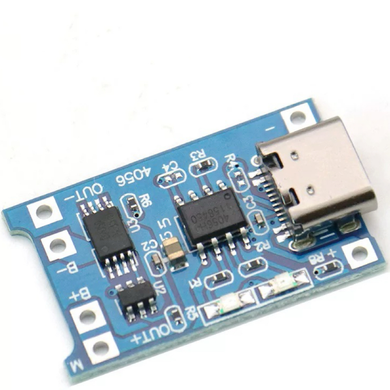
TP4056 Charging Module Pinout, Working, and Applications
2026-01-23
Everything You Need To Know About ARE1309 Relay

2025-04-23
Complete Guide to the 220 Ohm Resistor
220 Ohm Resistor
2025-07-28
120 Ohm Resistor- Specifications, Applications, and Features
2025-05-12
Guide To The AMS1117 Voltage Regulator
AMS1117 Voltage Regulator Circuit
2025-08-17