



 BOM
BOM Cart
Cart Product Catalog
VS1053 is a powerful audio decoder and encoder designed for embedded audio applications. It supports multiple audio formats, including MP3, Ogg Vorbis, AAC, WMA, FLAC, WAV, and MIDI, while also providing audio recording capabilities through its integrated ADC. With an 18-bit stereo DAC, headphone amplifier, serial interfaces, GPIO, and flexible audio processing functions, VS1053 can handle many audio tasks in a single chip.
This article introduces the VS1053, including its pinout, specifications, key features, supported audio formats, applications, alternative devices, and VS1053 MP3 audio player module. It also explains how to connect and use a VS1053 module with Arduino for embedded audio playback and recording projects.
7. VS1053 MP3 Audio Player Module Decoder Board
8. How to Use VS1053 MP3 Audio Player Module with Arduino?
9. Frequently Asked Questions [FAQ]
What is VS1053?
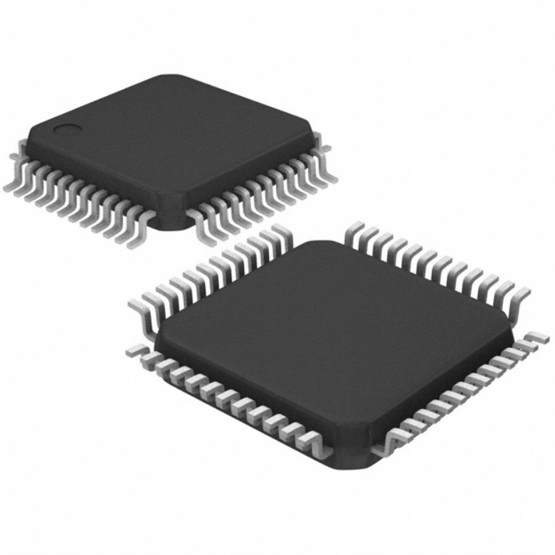
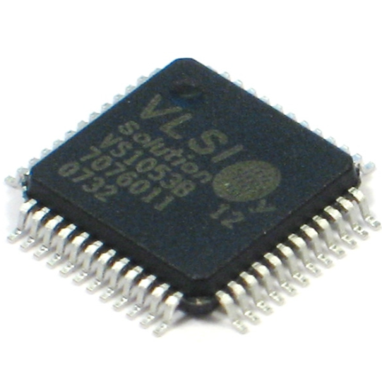
VS 1053 is a high-performance single-chip audio decoder and encoder from VLSI Solution. It supports Ogg Vorbis, MP3, AAC, WMA, FLAC, WAV, and MIDI decoding, as well as PCM, IMA ADPCM, and Ogg Vorbis encoding.
The device integrates a low-power VS_DSP4 processor, memory, serial interfaces, GPIO, UART, stereo ADC, 18-bit DAC, and earphone amplifier. It receives audio data through a serial input interface, processes it internally, and converts decoded audio into analog left and right outputs.
With microphone and line-in support, VS1053 can be used for both audio playback and recording. Its user RAM also allows additional functions such as DSP effects and application-specific software.
VS1053 Pinout
The VS 1053 is available in a 48-pin LQFP package. Its pins include power supplies, analog audio connections, serial interfaces, clock connections, GPIO, UART, and control signals.
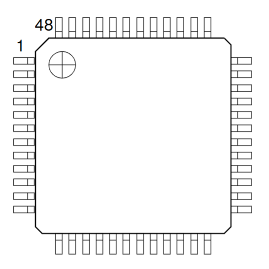
Pin | Pad Name | Type | Function |
1 | MICP LINE1 | AI | Positive differential microphone input / Line-in 1 |
2 | MICN | AI | Negative differential microphone input |
3 | XRESET | DI | Active-low asynchronous reset |
4 | DGNDO | DGND | Core and I/O ground |
5 | CVDDO | CPWR | Core power supply |
6 | IOVDDO | IOPWR | I/O power supply |
7 | CVDD1 | CPWR | Core power supply |
8 | DREQ | DO | Data request output |
9 | GPIO2 DCLK | DIO | GPIO2 / serial data clock |
10 | GPIO3 SDATA | DIO | GPIO3 / serial data input |
11 | GPIO6 I2S_SCLK | DIO | GPIO6 / I²S serial clock |
12 | GPIO7 I2S_SDATA | DIO | GPIO7 / I²S serial data |
13 | XDCS BSYNC | DI | Data chip select / byte synchronization |
14 | IOVDD1 | IOPWR | I/O power supply |
15 | VCO | DO | Clock VCO output, test only |
16 | DGND1 | DGND | Core and I/O ground |
17 | XTALO | AO | Crystal output |
18 | XTALI | AI | Crystal input |
19 | IOVDD2 | IOPWR | I/O power supply |
20 | DGND2 | DGND | Core and I/O ground |
21 | DGND3 | DGND | Core and I/O ground |
22 | DGND4 | DGND | Core and I/O ground |
23 | XCS | DI | Control chip select, active low |
24 | CVDD2 | CPWR | Core power supply |
25 | GPIO5 I2S_MCLK | DIO | GPIO5 / I²S master clock |
26 | RX | DI | UART receive |
27 | TX | DO | UART transmit |
28 | SCLK | DI | Serial bus clock |
29 | SI | DI | Serial input |
30 | SO | DO | Serial output |
31 | CVDD3 | CPWR | Core power supply |
32 | XTEST | DI | Reserved test input |
33 | GPIO0 | DIO | General-purpose I/O / SPIBOOT |
34 | GPIO1 | DIO | General-purpose I/O |
35 | GND | DGND | I/O ground |
36 | GPIO4 I2S_LROUT | DIO | GPIO4 / I²S left-right output |
37 | AGNDO | APWR | Analog ground |
38 | AVDDO | APWR | Analog power supply |
39 | RIGHT | AO | Right audio output |
40 | AGND1 | APWR | Analog ground |
41 | AGND2 | APWR | Analog ground |
42 | GBUF | AO | Common headphone buffer; do not connect to ground |
43 | AVDD1 | APWR | Analog power supply |
44 | RCAP | AIO | Analog reference/capacitor connection |
45 | AVDD2 | APWR | Analog power supply |
46 | LEFT | AO | Left audio output |
47 | AGND3 | APWR | Analog ground |
48 | LINE2 | AI | Line-in 2 / right channel |
Important VS1053 Pins
XCS and XDCS: These two chip-select signals separate control commands from audio data transfers. The host controller uses XCS for the control interface and XDCS for the data interface.
DREQ: DREQ tells the host controller when the device is ready to receive more data. An Arduino or other MCU should monitor this signal when sending an audio stream.
SCLK, SI, and SO: These signals form the main serial interface used for configuration and data communication.
LEFT and RIGHT: These are the analog left and right audio outputs. Can connect them to an external audio amplifier or suitable headphone circuitry.
MICP/LINE1, MICN, and LINE2: These pins provide analog audio input connections for microphone and line-level recording applications.
GBUF: This is the common headphone buffer output and should not connect directly to ground.
VS1053 Specifications
The chip uses separate analog, digital, and I/O supply domains. This arrangement helps isolate sensitive analog audio circuitry from digital processing and interface activity.
Parameter | Value |
Type | Audio |
Analog Supply Voltage | 2.5V~3.6V |
Digital Supply Voltage | 1.7V~1.85V |
Operating Temperature | -30°C~85°C |
Data Interface | I²S |
Resolution | 18-bit |
ADCs / DACs | 1/1 |
Mounting Type | Surface Mount |
Package | 48-LQFP |
Supplier Package | 48-LQFP (7×7 mm) |
Sigma-Delta | Yes |
VS1053 Applications
VS 1053 audio playback is suitable for embedded MP3 players, portable music devices, audio development boards, and other systems that need hardware-assisted decoding. Its support for several compressed audio formats allows one platform to handle different types of audio files.
Audio recording can use the integrated stereo ADC and analog input circuitry to capture microphone or line-level signals. PCM and IMA ADPCM encoding are supported, while can add Ogg Vorbis encoding through software.
Streaming applications can receive MP3 or WAV data from a host processor or communication system and decode the stream in real time. This makes it useful in network audio players and embedded streaming equipment.
MIDI applications can use General MIDI and SP-MIDI support for electronic instruments, educational devices, sound modules, and other systems requiring MIDI playback.
Voice and audio systems can combine microphone input, audio processing, decoding, and analog output in one device. The available user RAM also allows application-specific DSP functions to be added.
Other applications include:
· Portable MP3 players
· Internet and network audio players
· Voice recording equipment
· Embedded audio systems
· MIDI playback devices
· Audio development boards
· Digital music equipment
· Audio streaming products
· Microcontroller-based sound systems
· DSP audio-effect applications
VS1053 Features
Audio decoding supports a wide range of popular formats, including Ogg Vorbis, MP3, MP1/MP2, AAC-LC, HE-AAC v2, WMA, General MIDI, SP-MIDI, FLAC, and WAV with PCM or IMA ADPCM.
Audio encoding supports Ogg Vorbis through a software plugin, as well as stereo IMA ADPCM and PCM encoding, making the device suitable for both playback and recording.
Streaming support allows MP3 and WAV data to be processed continuously, which is useful for embedded players and streaming applications.
Audio processing includes EarSpeaker spatial processing, bass and treble controls, and zero-cross detection for smooth volume changes. The integrated stereo DAC provides high-quality output with no phase error between channels.
Clock and power features include operation with a 12~13 MHz or 24~26 MHz clock, an internal PLL clock multiplier, and low-power operation. Separate analog, digital, and I/O supply voltages help improve audio system performance.
Audio output includes a stereo earphone driver capable of driving a 30 Ω load, quiet power-on and power-off, and an I²S output interface for an external DAC.
Software functions include on-chip RAM for user code and data, serial control and data interfaces, SPI flash boot support, UART debugging, and up to 8 GPIO pins. The chip can also operate as a slave co-processor and support additional functions through software.
Package is lead-free and RoHS compliant, making the device suitable for various embedded audio products.
VS1053 Alternative
VS1003
VS1003 is an earlier audio decoder and encoder solution that supports MP3, WMA, MIDI, and ADPCM. It also uses the VS_DSP4 architecture and provides a stereo DAC, headphone amplifier, UART, and serial control/data interfaces.
Compared with VS1053, it has less user instruction RAM and fewer GPIO pins. Its ADC is mono rather than the more capable stereo ADC provided by VS1053. Therefore, the two devices are aimed at different levels of audio functionality.
VS1063
VS1063 is another member of the VS10xx audio family. It provides 18-bit audio conversion and supports a wide range of embedded audio functions. It uses a 48-LQFP package and operates with similar digital and analog supply ranges.
Parameter | VS1053 | VS1003 | VS1063 |
Type | Audio | Audio | Audio |
Sigma-Delta | Yes | — | No |
Analog Supply | 2.5V~3.6V | — | 2.5V~3.6V / 3.3V~3.6V |
Digital Supply | 1.7V~1.85V | — | 1.7V~1.85V |
Operating Temperature | -30°C~85°C | — | -30°C~85°C |
Data Interface | I²S | Serial | I²C, Serial |
Resolution | 18-bit | 18-bit | 18-bit |
ADC / DAC | 1/1 | 1/1 | 1/1 |
Package | 48-LQFP | — | 48-LQFP |
Package Size | 7×7 mm | — | 7×7 mm |
The appropriate device depends on the required audio formats, recording functions, interfaces, memory resources, and software features. Always check the specific device documentation and hardware compatibility before designing a replacement circuit.
VS1053 MP3 Audio Player Module Decoder Board
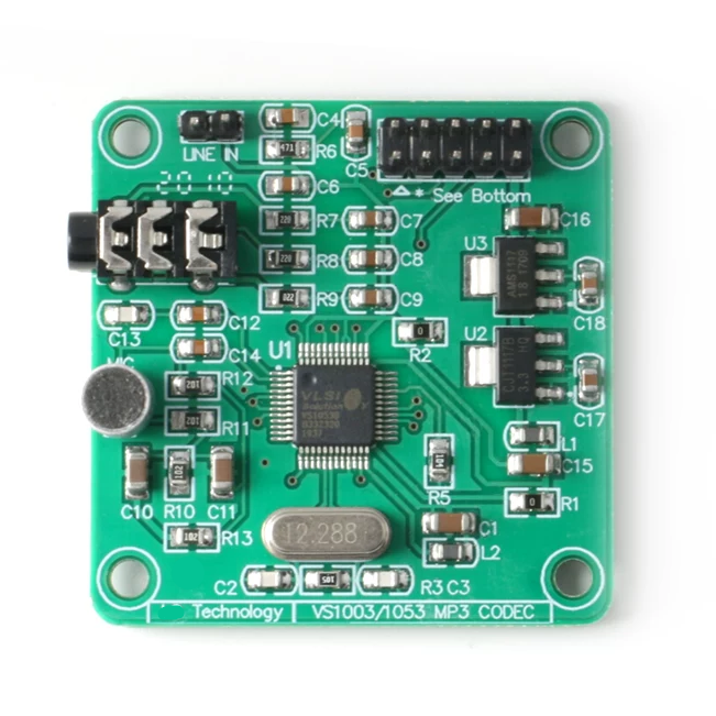
The VS1053 MP3 audio player module integrates the audio decoder with the supporting circuitry required for development and embedded applications. It can play multiple audio formats and can also support Ogg Vorbis real-time encoding and recording.
The board typically provides a headphone/audio output, microphone input, and line-in interface. A power indicator is also included for convenient operation.
A typical module configuration includes an onboard 3.3 V and 1.8 V regulator, such as the AMS1117-based power circuitry, allowing the module to be powered from a 5 V supply. The board also uses a 12.288 MHz crystal as the primary audio clock source.
Module Feature | Description |
Main Chip | VS1053 |
Power Input | +5 VDC |
Onboard Regulators | 3.3 V / 1.8 V |
Crystal | 12.288 MHz |
Audio Output | Headphone / audio output |
Microphone | Recording input |
Line Input | Line-in interface |
Indicator | Power LED |
Controller | AVR-based development board configuration |
Programming | ISP interface |
The module is useful for experimenting with audio decoding, recording, streaming, and microcontroller-controlled playback without designing the complete analog and power circuitry from scratch.
How to Use VS1053 MP3 Audio Player Module with Arduino?
The VS1053 module can be controlled by an Arduino through its serial interface. The Arduino acts as the host controller while the decoder board performs the computationally intensive audio processing.
A typical connection uses the SPI interface for control and audio data transfer. The exact Arduino pins depend on the Arduino board being used.
Basic Connection
VS 1053 Module | Arduino Function |
VCC | 5 V module supply, if supported by the module |
GND | GND |
SCLK | SPI Clock |
MOSI / SI | SPI MOSI |
MISO / SO | SPI MISO |
XCS | Control Chip Select |
XDCS | Data Chip Select |
DREQ | Data Request GPIO |
XRESET | Reset GPIO |
LEFT / RIGHT | Audio output |
The Arduino first initializes the VS1053, configures the required control registers, and then prepares the decoder for playback. Audio data is transferred through the serial data interface.
DREQ is particularly important during playback. The host should send data only when the decoder indicates that it is ready. This prevents the input buffer from being overloaded and allows the decoder to process the stream continuously.
For an MP3 player, the general process is:
1. Power the module and establish a common ground.
2. Initialize the SPI interface.
3. Reset the decoder.
4. Configure the VS1053 control registers.
5. Select the required audio file or stream.
6. Read audio data in blocks.
7. Monitor DREQ.
8. Send data through the VS1053 data interface.
9. Connect the audio output to headphones or an amplifier.
When using an Arduino library, the software normally handles the low-level SPI transactions, register configuration, decoder initialization, and DREQ monitoring. This allows the application code to concentrate on file selection, playback control, volume adjustment, and user interaction.
Because different VS 1053 modules may use different onboard regulators and connector layouts, verify the module's voltage requirements before connecting it directly to an Arduino.
Frequently Asked Questions [FAQ]
What audio formats does VS1053 support?
VS 1053 supports Ogg Vorbis, MP3, AAC, WMA, WAV, MIDI, and FLAC through its built-in decoder functions and software-plugin capabilities. It also supports PCM and IMA ADPCM encoding, while Ogg Vorbis encoding can be added through software. This makes it suitable for both playback and recording applications.
Can VS1053 record audio?
Yes. VS 1053 includes an integrated variable-sample-rate stereo ADC with microphone and line-level input capability. It can encode stereo PCM and IMA ADPCM, while Ogg Vorbis encoding is available through a software plugin. This allows one device to handle both audio playback and recording.
Is VS1053 compatible with Arduino?
Yes. Can control a VS1053 module by an Arduino through its serial interface, typically using SPI for control and audio data. Additional GPIO connections are required for signals such as XCS, XDCS, DREQ, and reset. The exact wiring depends on the Arduino board and VS 1053 module.
What is the difference between VS1053 and VS1003?
VS1053 provides a broader set of audio capabilities than VS1003, including support for additional formats and stereo ADC functionality. It also provides more user memory and GPIO resources. VS1003 is an earlier device focused on MP3, WMA, MIDI, and ADPCM-related applications.
What does an audio decoder do?
An audio decoder converts compressed or encoded digital audio data into a format that can be processed and played back. For example, an MP3 decoder processes MP3 data and reconstructs digital audio samples. These samples can then be sent to a DAC, amplifier, and speaker or headphones for listening.
What is the best amplifier module?
There is no single best amplifier module for every application. The appropriate choice depends on speaker impedance, required output power, supply voltage, efficiency, size, and audio quality. Class-D modules are commonly selected for compact projects because they provide high efficiency while delivering sufficient power for many speakers.
Why do I need a DAC?
A DAC, or digital-to-analog converter, changes digital audio samples into an analog electrical signal. Speakers and traditional analog amplifiers require this analog signal to produce sound. In an audio system, a DAC therefore provides the conversion between digitally processed music and the analog audio signal used by the output stage.
What is the best audio codec for high-quality sound?
There is no universally best audio codec because sound quality depends on bitrate, sampling rate, source material, and application requirements. Lossless formats such as FLAC preserve the original audio data, while high-bitrate AAC or other modern lossy codecs can provide high perceived quality with significantly smaller file sizes.
Conclusion
VS1053 combines audio decoding, recording, digital signal processing, ADC, DAC, serial interfaces, GPIO, and headphone amplification in a single audio processor. Its support for MP3, Ogg Vorbis, AAC, WMA, WAV, MIDI, and FLAC makes it useful for embedded multimedia applications.
The VS 1053 MP3 Audio Player Module simplifies development by adding power regulation, clock circuitry, audio inputs, and outputs around the main chip. With SPI control and DREQ-based data handling, it can be connected to Arduino and other microcontrollers for portable players, recording equipment, streaming systems, MIDI devices, and embedded audio projects.
Read More:
1. MAX4466 Electret Microphone Amplifier Module Board Adjustable
2. DS3231 RTC Module – High Precision Real Time Clock
3. SX1276 LoRa Transceiver: Pinout and Wireless Lora Module
VS1053 Datasheet:
HOT NEWS
TP4056 Charging Module Pinout, Working, and Applications
TP4056 Charging Module Pinout, Working, and Applications
2026-01-23
LR41 Battery Guide: Specifications, Equivalents, and Uses
LR41 Battery Specifications, Equivalents, and Uses
2025-12-14
Understanding A 0603 Resistor
0603 resistor,dimensions,marking code, values
2025-05-29
MT3608 Boost Converter - An In-Depth Guide
MT3608 Boost Converter
2025-09-04
The 0402 Resistor: A Comprehensive Guide
0402 Resistor
2025-05-06
Complete Guide to the 220 Ohm Resistor
220 Ohm Resistor
2025-07-28
Understanding The CD4051 Analog Multiplexer
CD4051 analog multiplexer
2025-06-30
What Is A 1206 Resistor?
1206 resistor dimensions,footprint,value
2025-06-05
Guide To The XL6009 Boost Converter
XL6009 Boost Converter
2025-09-05
120 Ohm Resistor- Specifications, Applications, and Features
2025-05-12